
Concept explainers
Videos
The value of node voltages
Answer to Problem 4.74HP
The value of voltage
Explanation of Solution
Calculation:
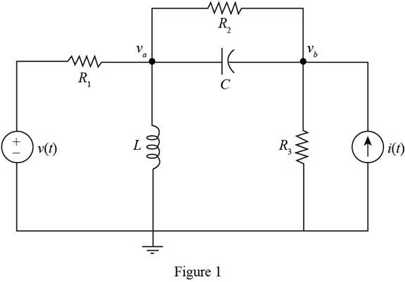
The given diagram is shown in Figure 1
The conversion from
The conversion from
The conversion from
The conversion from
The expression for the source voltage is,
The general for the time-dependent expression of voltage is given by
From above and from equation (1) the value of angular frequency is given by
The general form for the polar form of the voltage is given by
From equation (1) and above, the polar form of the supply voltage is given by
The expression for the source current is given by
The general expression for the phasor form of the current is given by
From equation (3) and equation (1), the phasor form of the current is given by
The expression to calculate the inductive impedance of the inductor is given by
Substitute
The expression to calculate the capacitive reactance is given by,
Substitute
Mark the values and redraw the circuit for the phasor form.
The required diagram is shown in Figure 2
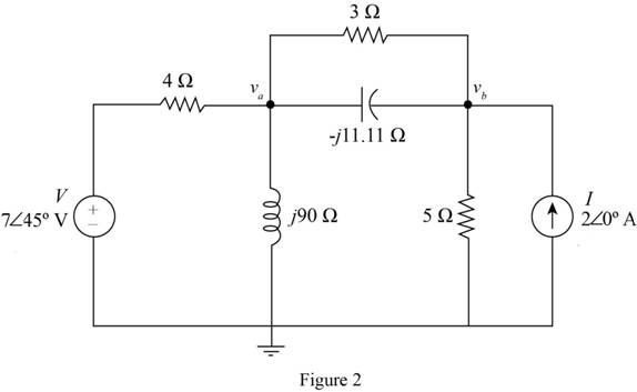
Apply KCL at node
Solve further as
Apply KCL at node
Substitute
Solve further as
From above and from equation (2), the time-dependent form of the node voltage
Substitute
Substitute
Solve further as
From above and from equation (2), the time-dependent form of the node voltage
Substitute
Conclusion:
Therefore, the value of voltage
Want to see more full solutions like this?
Chapter 4 Solutions
Principles and Applications of Electrical Engineering


- P4.30. Consider the circuit of Figure P4.30 in which the switch has been closed for a long time prior to t=0. Determine the values of v C (t) before t=0 and a long time after t=0. Also, determine the time constant after the switch opens and expressions for v C (t). Sketch v C (t) to scale versus time for -4sts16 s. 2 MA 30 V 2 uF I MO Figure P4.30arrow_forwardSelect an answer4. Two base signals for a quadrature system are:A. sin (w_c t) and cos (2w_c t)B. sin (w_c t) and cos (w_c t)C. sin (1/2 w_c t) and cos (w_c t)D. cos (w_1 t) and cos (w_2 t)arrow_forwardJust like resistors, impedance values can be combined in series or in parallel. We combine them in the same way as combining resistors, i.e., for the series connection: Zeg Z1+22+ Z3+.... For the parallel connection: Zeq = (Z+Z+Z3+...) What is the equivalent impedance of the following circuit? (Hint: you can use scientific calculator or MatLab to perform calculations involving complex numbers.) L 50 £2 300 1000 MO 400 200 102.2+19.8j O 102.2-19.8j -102.2+19.8j O-102.2 19.8jarrow_forward
- A Hay's bridge uses a standard capacitor of C4 = 0.02 mF and operates at a supply frequency of 800 Hz. Balance is achieved when R2 =0.54kn ,R3= 3.8kN, and R4 =100 Q. Find the unknown Resistance R1 and unknown inductance L1. unknown Resistance R1 unknown Inductance L1arrow_forwardPLEASE HELP THIS ASAPP (Superpositon Theorem)arrow_forwardP4.42. The switch shown in Figure P4.42 has been closed for a long time prior to t=0, then it opens at t=0 and closes again at t=1 s. Find i L (t) for all t. 6H 121 Figure P4.42arrow_forward
- Determine the equivalent inductance and equivalent current of the inductive circuit in Figure Q4. If L5 is replaced with a capacitor of 0.55 mF, how would it affect the branch current? The alternating Voltage source has an amplitude of 25 Vm.arrow_forward4.61 In the circuit shown in Figure P4.61: VS1 = 15 V Vs2 = 9 V Rs1 = 130 Q R$2 = 290 22 R₁ = 1.1 kQ2 R₂ = 700 Q L = 17 mH C = 0.35 µF Determine the voltage vc across the capacitor and the current i, through the inductor as t → ∞o. Rs1 Vsi t=0 iL LR₁ Figure P4.61 CVC R$2 с +21 ww R₂ V s2arrow_forwardA 0.7-H inductor is connected in series with a 9-ohm resistor. If the connection is energized from an 11-V DC source, determine which among the following is a differential equation describing the current / in the circuit at any time t. O A. di dt O B. di 8 dt O C. di dt OD. di dt 90 + -i = 7 + + + 110 7 7 110 7 90 1 = i = i = 110 7 90 7 90 7 110arrow_forward
 Introductory Circuit Analysis (13th Edition)Electrical EngineeringISBN:9780133923605Author:Robert L. BoylestadPublisher:PEARSON
 Delmar's Standard Textbook Of ElectricityElectrical EngineeringISBN:9781337900348Author:Stephen L. HermanPublisher:Cengage Learning
 Programmable Logic ControllersElectrical EngineeringISBN:9780073373843Author:Frank D. PetruzellaPublisher:McGraw-Hill Education
 Fundamentals of Electric CircuitsElectrical EngineeringISBN:9780078028229Author:Charles K Alexander, Matthew SadikuPublisher:McGraw-Hill Education
 Electric Circuits. (11th Edition)Electrical EngineeringISBN:9780134746968Author:James W. Nilsson, Susan RiedelPublisher:PEARSON
 Engineering ElectromagneticsElectrical EngineeringISBN:9780078028151Author:Hayt, William H. (william Hart), Jr, BUCK, John A.Publisher:Mcgraw-hill Education,