
Videos
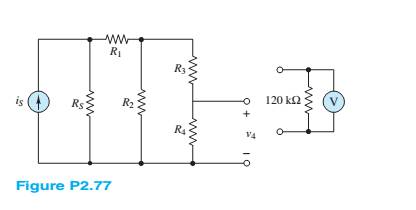
A voltmeter is used to determine the voltage acrossa resistive element in the circuit of Figure P2.77. The instrument is modeled by an ideal voltmeter in parallel with a
a.
b.
c.
d.
(a)
The voltage across R4 with and without voltmeter for the given value.
Answer to Problem 2.77HP
Without the voltmeter
With the voltmeter:
Explanation of Solution
Given information:
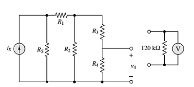
The given circuit is shown below.
Calculation:
Assuming that voltmeter is ideal in parallel with 120-ohm resister.
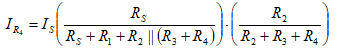
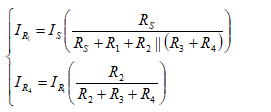
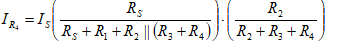
First develop an expression for VR4 in terms of R4 ,using current division
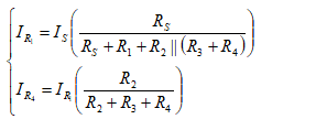
Therefore,
Hence,without the voltmeter
Now find the voltage drop across
With the voltmeter:
(b)
The voltage across R4 with and without voltmeter for the given value.
Answer to Problem 2.77HP
Without the voltmeter
With the voltmeter:
Explanation of Solution
The given circuit is shown below.

Calculation:
Assuming that voltmeter is ideal in parallel with 120-ohm resister.
First develop an expression for VR4 in terms of R4, using current division.
Therefore,
Hence, without the voltmeter
Now, it is must find that the voltage drop across
With the voltmeter:
(c)
The voltage across R4 with and without voltmeter for the given value.
Answer to Problem 2.77HP
Without the voltmeter
With the voltmeter:
Explanation of Solution
The given circuit is shown below.

Calculation:
Assuming that voltmeter is ideal in parallel with 120-ohm resister.
First develop an expression for VR4 in terms of R4, using current division.
Therefore,
Hence, without the voltmeter
Now, it is must find that the voltage drop across
With the voltmeter:
(d)
The voltage across R4 with and without voltmeter for the given value.
Answer to Problem 2.77HP
Without the voltmeter
With the voltmeter:
Explanation of Solution
The given circuit is shown below.

Calculation:
Assuming that voltmeter is ideal in parallel with 120-ohm resister.
First develop an expression for VR4 in terms of R4 ,using current division
Therefore
Hence without the voltmeter
Now it is must find that the voltage drop across
With the voltmeter:
Want to see more full solutions like this?
Chapter 2 Solutions
Principles and Applications of Electrical Engineering


- A student wants to measure the electric potential difference across the resistor R2 for the circuit below. R, D A R2 Where should a student hook up a voltmeter to measure the electric potential difference across resistor R2? From point B to point D From point A to point D From point B to point C From point A to point Carrow_forward150 100 + VA- a -4V AVA -7V 81. B b Figure 2 shows a simplified model of a gas-discharge lamp. One characteristic of these lamps is that they exhibit negative resistance; in other words, as current increases the voltage drops further, making such lamps inherently unstable. As such, a current-limiting ballast is required. For the connection shown in the figure: 1. Find the equivalent Thevenin circuit of the lamp. 2. Find the ballast resistance needed to limit the current drawn from a 24-volt source to 6 amperes.arrow_forwardINSTRUCTIONS: Solve the following problems. Show and COMPLETE solutions. Draw all CIRCUIT DIAGRAMS or the equivalent circuit (dummy circuit) as the case may be. Write your solutions on sheet/s of short bond paper. A battery is to consist of 20 identical cells. The emf of each cell is 1.5 V and the internal resistance is 0.20 ohm. This battery will be used to supply power to a 10 ohm lamp. Determine the current on the lamp if:1. The 20 cells are connected in series 2. The 20 cells are connected in parallel 3. The 20 cells are arranged 5 cells in series in 4 parallel rows.arrow_forward
- Two resistive coils R1, R2 are connected in parallel across 140 V DC supply and takes 12 A from the supply. The power dissipated in R1 is 650 W, then the value of resistive coil R1 isarrow_forwardWhich of the following statements regarding circuits are true? To find resistance in a parallel circuit, you must sum the individual resitances The direction of conventional current is the direction of positive charge flow. In a circuit, electrons flow from high potential energy (at the negative terminal) to low potential energy (at the positive terminal). When electricity is passed through a lightbulb, the electrons are 'used up' by the bulb. All voltages in a loop sum to 12V The current that flows into a resistor is the same as the current that flows out. To 'short circuit' something means there is an alternate path of less resistance for the current to flow. Switching on a light happens immediately because electrons move from the power source to the bulb incredibly quickly. A 'kilowatt-hour' is a unit of power, not energy.arrow_forwardA battery with & = 2.00 V and no internal resistance supplies current to the circuit shown in the figure below. When the double-throw switch S is open as shown in the figure, the current in the battery is 1.04 mA. When the switch is closed in position a, the current in the battery is 1.30 mA. When the switch is closed in position b, the current in the battery is 2.10 mA. Find the following resistances. ww R₁ R₂ R₂ TE da S ob R₂ (a) R₁ 1.92 x Your response differs significantly from the correct answer. Rework your solution from the beginning and check each step carefully, k (b) R₂ 1538.46 x Your response differs significantly from the correct answer. Rework your solution from the beginning and check each step carefully. k (c) R3 ΚΩarrow_forward
- A 25mv, 2mA dArsonval movement is to be used in voltmeter whose full scale reading is 100v. The resistance inserted by 100v meter into circuit is Select one: a. 1 x 10⁶ ohm b. None of all c. 1 x 10⁴ ohm d. 1 x 10⁵ ohm e. 1 x 10³ ohmarrow_forwardA student wants to measure the electric potential difference across the battery for the circuit below. R, A D C R2 Except from point A to point D, where should a student hook up a voltmeter to measure the electric potential difference across the battery? O From point D to point C From point B to point C From point B or point D O From point A to point Barrow_forwardIn the circuit shown below, if R1=5 ohm, R2=10 ohm and Vin = 2V. Then the current (I) will equal to: Vino Vout R1 R2 O a. -0.6A O b. 0.4A O c. -0.2A O d. -0.4A Oe. 0.6Aarrow_forward
- The voltage difference between points a and b in the circuit below is provided by a battery that has a voltage Vab = 24 volts. (The battery is not in the picture.) Find the current across R. The individual resistances are R₁ = 2.00, R₂ = 4.00, R3 = 3.0 Q. R4 = 1.0 Q, and R5 = 5.0 0. a O a. 0.70 A O b. 1.3 A OC. 0.40 A O d. 1.6 A O e. 1.0 A ww R₁ R₂ ww 2 www Rs www RA R₁ wwarrow_forwardDetermine the total resistance, Rī, and current, I, for the circuit in Figure Q1(b). 30V- RT 50Ω 2002 4092 7092 m Figure Q1(b) 3002 m 6092 [Answer: 22.430, 1.34A]arrow_forwardEach of the cells shown in the figure has an emf of 1.50 V and a 0.0750-ohm internalresistance. Find I1, I2, and I3.arrow_forward
 Introductory Circuit Analysis (13th Edition)Electrical EngineeringISBN:9780133923605Author:Robert L. BoylestadPublisher:PEARSON
 Delmar's Standard Textbook Of ElectricityElectrical EngineeringISBN:9781337900348Author:Stephen L. HermanPublisher:Cengage Learning
 Programmable Logic ControllersElectrical EngineeringISBN:9780073373843Author:Frank D. PetruzellaPublisher:McGraw-Hill Education
 Fundamentals of Electric CircuitsElectrical EngineeringISBN:9780078028229Author:Charles K Alexander, Matthew SadikuPublisher:McGraw-Hill Education
 Electric Circuits. (11th Edition)Electrical EngineeringISBN:9780134746968Author:James W. Nilsson, Susan RiedelPublisher:PEARSON
 Engineering ElectromagneticsElectrical EngineeringISBN:9780078028151Author:Hayt, William H. (william Hart), Jr, BUCK, John A.Publisher:Mcgraw-hill Education,